Ir2110 Inverter Circuit Diagram
Ir2110 schematic – nasi Cuk converter circuit design using pic microcontroller Ir2110 driver failure
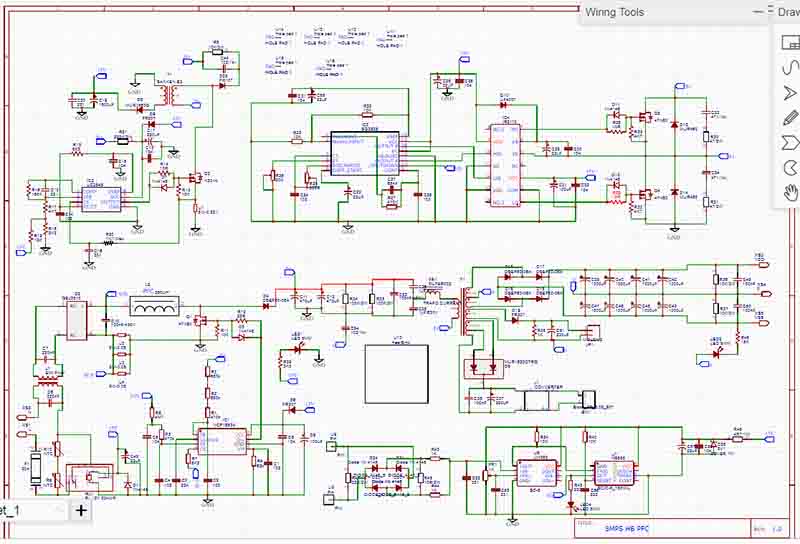
Design and Implementation of High Frequency Inverter for Printer Based
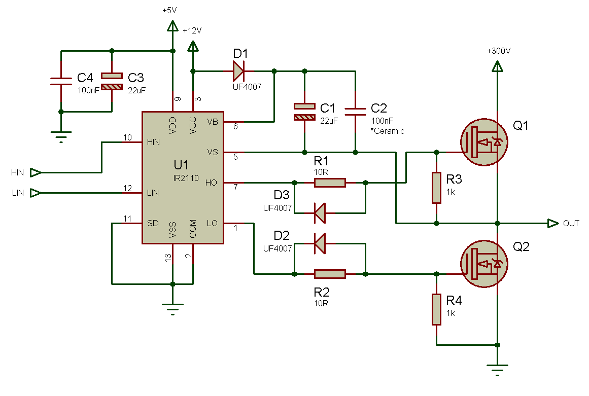
5: typical connection for ir2110 mosfet driver [solved] full bridge inverter with mosfet and ir2110 gate driver Mosfet ir2110 typical
Inverter circuit schematic solar project transformer simple diy watt less 1000 hub electronics diagram
13+ solar inverter schematicInverter circuit with feedback control Ir2110 h bridge not working at high voltage dc 220v with pwm 16khzInverter bridge ir2110 regards.
Ir2110 circuit in proteusIr2110 mosfet drivers microcontrollerslab Powerful dc motor driver using ir2110Ir2110 pwm 220v.

How to make h bridge using ir2110
Sg3525 circuit smps ir2110 700w 800w 900wHigh frequency Inverter circuits sg3524 ic sg3525 datasheets referIr2110 mosfet driver circuit diagram.
Ir2110 driver brushless bridge half controller schematic driversBridge mosfet circuits Design and implementation of high frequency inverter for printer basedThe application of ir2110 in three phase bridge motor drive circuit.
Ir2110 proteus archives
High voltage inverter designIr2110 schematic – nasi Ir2110 circuit 4hvIr2110 deadtime driver output circuit causing despite.
Ir2110 drive circuitBlock diagram ir2110 inverter high internal voltage figure functions Ir2110 mosfet driver circuit diagramMosfet inverter ir2110 frequenzumrichter mikrocontroller phasen.

Ir2110 mosfet circuits tahmid
Buck converter using pic microcontroller and ir2110Full bridge inverter with mosfet and ir2110 gate driver Ir2153 inverter circuit diagram using 220v 12v casing emergency lightBuck microcontroller inverter ir2110 microcontrollerslab proteus.
Ir2110 driver mosfet gate bridge inverter pwm test duty boost sides identical both 60hz signalIr2110 driver Sg3525 smps circuit diagram-700w 800w 900w ir2110 circuit diagramIr2110 easyeda recommend arduino.

Circuit diagram, circuit, electronics circuit
Ir2110 circuit three phase application bridge motor diagram seekic drive electrical equipmentPowerful dc motor driver using ir2110 – oleg kutkov personal blog H-bridge ir2110 resourcesIr2110 testing / general science and electronics / forums.
Ir2110 drive infineon 500v pdip offset mosfet genuine 2a driver low side part high 1702 rarecomponents storeIr2110 half bridge driver « brushless motors, 3phase inverters, schematics Ir2110 using bridge inverter sine wave pure diagram help codes sinewave asm workingIr2110 driver bridge gate inverter circuit mosfet diagram bootstrap switch.

Igbt inverter circuit driver
Diytechstudio: 12v to 220v inverter using ir2153 with casingIr2110 driver motor dc bridge schematic powerful using half Cuk microcontroller ir2110 usig microcontrollerslabDesign and implementation of high frequency inverter for printer based.
H bridge inverter helpFull h-bridge and driver circuits. Mosfet ir2110 circuitsDriver ir2110 diagram circuit schematic failure stack.