Induction Motor Control Circuit Diagram
Reversing three phase induction motors 3 phase induction motor driver vfd motor control circuit diagram pdf 3 phase induction motor driver vfd motor control circuit diagram pdf
Single Phase Induction Motor Direction Control using 8051
Induction circuit starter rotor stator circuitglobe shown Forward & reverse 3 phase ac motor control circuit diagram On/off electric motor control circuits
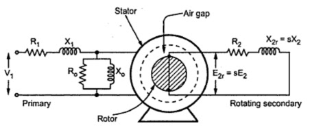
Induction motor circuit equivalent
Motor control ac circuits electric phase single off automation grasp principles induction majorMotor phase single circuit direction induction control using microcontroller v2 power connect Wiring direction electrical etechnog schematicsMotor protection induction phase system compressor diagram circuit wiring rotary circuitglobe converter working auxiliary contacts.
Induction circuit heater circuits diagram projects school small homemade project simple electronics wiring diy electrical electronic schematic high using postCircuit diagram of induction motor- (part Motor control induction speed circuit basic diagram seekicSpeed_control_for_induction_motor.

Motor control diagram wiring phase forward schematic panel circuit reverse ac pump starter electrical bradley allen induction delta star diagrams
Why starting current of induction motor is highInduction motor schematic diagram illustration 🔴 induction motor forward reverse circuit diagram 👥 tag your friends☑ ac induction motor control circuit.
How a 3 phase motor control circuit worksMotor phase speed induction circuit controller circuits diagram pwm three brushless electronic ic homemade ac arduino using regulator wiring input Phase diagram attainingMotor induction circuit starter phase automatic diagram project projects description stater.
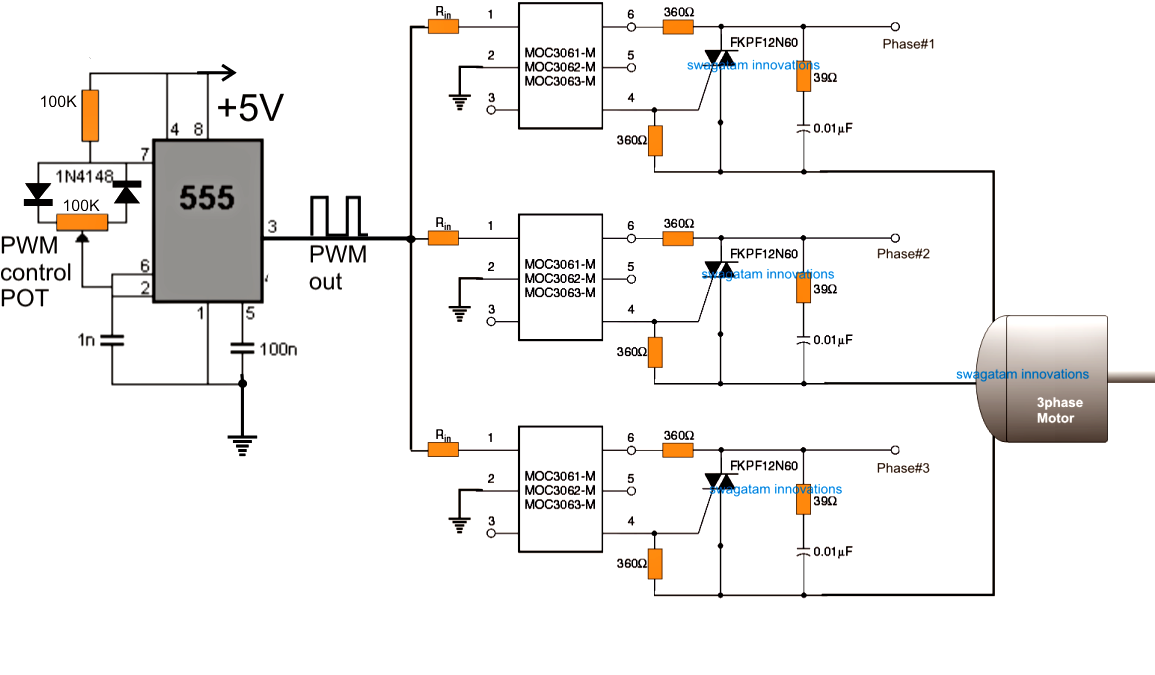
Induction motor phase speed control circuit controller pwm bridge based bldc board electronic esc schematic diagram arduino ic driver triac
3-phase ac induction motor controlSmall induction heater for school project Attaining high accuracy in motor controlAc lab.
Ac labDesign and development of a linear induction motor: circuit diagram Induction controller vfd☑ ac induction motor control circuit.

Motor induction electrical4u starting braking winding part starter drives circuit motors soft speed control electrical diagram windings engineering
Circuit motor phase diagram controlMotor control ac induction speed circuit phase single iron soldering electronic diagram motors diy electrical schematics technology choose board las Motor control circuit forward reverseInduction inverter connected.
Equivalent circuit of induction motor : part 1Induction system vfd torque 3 phase motor control circuit diagramCircuit control motor induction diagram speed pole shaded seekic single.

3 phase induction motor block diagram
Motor control circuit diagram focus on reverseProtection circuit of induction motor/overload protection of induction Induction_motor_control3 phase induction motor speed controller circuit.
Single phase induction motor direction control using 8051Equivalent circuit diagram of induction motor (part 1) 3 phase induction motor speed controller circuit ~ electronic circuitMotor phase single induction control circuit diagram theory electronic ac connection 2010 grinder bench dead cap.

Motor induction starting current circuit high model why shown figure
Phase induction ac motor control three block nxp diagram kv seriesReversing induction wiring motors contactor electrical electricala2z Phase motor circuit control worksInduction motor protection system.
Induction motor soft starter circuit diagramCircuit diagram of induction motor connected to an inverter. Starting of an induction motorInduction overload.

Induction motor schematic diagram ac illustration
3 phase induction motor starterBlock diagram of induction motor control. Vfd motor phase induction diagram wiring circuit block plc control fig motors controlling using.
.