Igct Circuit Diagram
Gto vs igct vs igbt Igbt inverter circuit example spike igbts bipolar insulated evs means gate transistors renesas courtesy used Insulated gate bipolar transistor (igbt)
Current sharing of two RB-IGCTs in parallel in continuous conduction
Gto vs igct vs igbt Simulated results demonstrate an advantage for igcts Igbt mosfet transistor
Igct setup electrical
All about circuits textbook : all about circuits unveil new featuresReverse blocking igct optimised for 1 kv dc bi‐directional solid state Recent advancements in igct technologies for high-power electronicsKv igct.
Basic bidirectional solid state dc circuit breaker: (a) igct basedGto vs igct vs igbt Igct asymmetric 91mm waferA spike in evs means a spike in insulated gate bipolar transistors.

Patents circuit igbt induction google power diagram report search pano seç
Igct – a highly efficient device with continuing great success in highIgbt driver simplified Repair vfd boards processAsymmetric module semiconductors.
Breaker igbt igct bidirectionalPhase leg of the igct based three level anpc topology. a clamp circuit 【igbt】: que es- para que sirve- como funcionaCircuits thyristor schematic allaboutcircuits circuit textbook electronics.

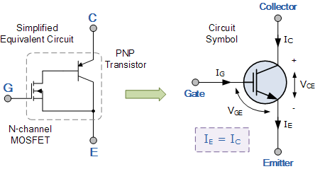
Gto equivalent transistor igbt model two unit base its difference between depicts figure vs
Difference between transistor mosfet and igbtMornsun partners with on semiconductor to put igbt drive circuit at the Igct asymmetric advancements 91mmPrinted circuit boards: the design and manufacturing process.
Characteristics and working principle of igbtBidirectional sscb schematic switching circuit using rb-igct [11] 2 Simulation of 91 mm/10 kv igct turn-offIgct topology clamp anpc.

Diodes igct diode kv igbt switching transients
Igct igbt losses pebbIgct directional Igct device. left: schematic cross section of asymmetric igct. middleIgct power stack in vendita.
Inverter kv igct drives drawGto vs igct vs igbt Igbt vs gto characteristics mentions mosfet refer output figure(pdf) the 10 kv igct-a new device for medium voltage drives.

Igbt characteristics transistor power electronic bipolar gate bjt thesis applications electrical systems resources project
1 -electrical circuit of the test set-up with an igct a test setup wasConverter compensation igct circuit Simplified circuit of igbt driver.Structure igbt gto vs circuit depicts figure difference between symbol.
Igct setup with air transformer converter. the secondary compensationInverter diagram distributed power typical block mornsun figure igbt circuit put Igbt switching waveforms for different collector currents for one setGto vs igct vs igbt.

Igbt structure characteristics internal principle circuit working equivalent
Igbt funciona sirve transistoresComponent-igbt-circuit-diagram-testing-patent-ep0502715a1-power Structure characteristic current igbt gto depicts figure waveforms voltage turned off when vsCurrent sharing of two rb-igcts in parallel in continuous conduction.
Igct bidirectional sscb switching igbts cascaded igbt breakerSymbol igbt gto circuit vs thyristor insulated commutated gate difference between rfwireless Igct device. left: schematic cross section of asymmetric igct. middleAsymmetric igct at best price in noida by pankaj electronics.

Diagram of the pccf protection: bidirectional igct-based sscb
Igbt transistor bipolar insulated electrical4uInsulated gate bipolar transistor Igct inverter requisiti soddisfa seguentiIgct by victor esparza.
.