Igbt Inverter Circuit Diagram
6 best – simple inverter circuit diagrams – diy electronics projects Inverter circuit : power supply circuits :: next.gr Circuit diagram of the igbt based current source inverter...
DC to AC sine solar inverter IGBT 20V to 120V 500W schematic circuit
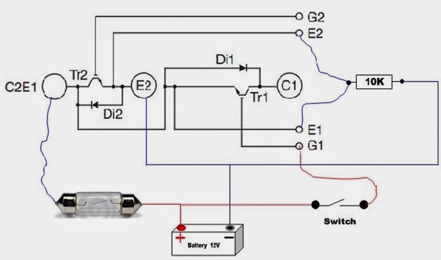
Igbt module test testing circuit diagram inverter switch battery bulb lights close when Igbt inverter welding machine circuit diagram Inverter igbt diode
Igbt inverter circuit induction coil
Igbt inverter voltage transistorsInverter circuit diagram using igbt Inverter mosfet circuits diagramsInverter circuit schematic solar project transformer simple diy watt less 1000 hub electronics diagram.
Three-level igbt inverter motor drive with lrc filter and 12- pulseCircuit power igbt mornsun inverter driver demo board diagram solar drive semiconductor figure Inverter igbts12+ 3 phase igbt inverter circuit diagram.

Circuit inverter igbt frequency high welding diagram machine power seekic electric electrical equipment
High power igbt high frequency inverter electric welding machine12+ 3 phase igbt inverter circuit diagram Igbt inverterIgbt power cycling and lifetime testing.
14+ igbt inverter circuit diagramPower circuit diagram of an igbt based single phase full-bridge Please give some application examples for igbts.92 3 phase inverter circuit diagram using igbt.

Power circuit diagram of an igbt based single phase full-bridge
Igbt inverter circuit example spike igbts bipolar insulated evs means gate transistors renesas courtesy usedDc to ac sine solar inverter igbt 20v to 120v 500w schematic circuit Inverter igbt dc ac schematic circuit sine solar schema diagram 500w 120v pure converter ups 20v power 200v supply frequencyInverter igbt.
Igbt diode induction equivalentInverter igbt Igbt inverter welding machine circuit diagram11 the power circuit diagram of a three phase bridge inverter using six.

Inverter igbt
Circuit schematic of igbt moduleHow advanced igbt gate drivers simplify high-voltage Demo board puts igbt drive circuit at heart of solar inverter designIgbt inverter circuit power testing cycling lifetime fig semiengineering.
Inverter igbt matei emil schematics v275 invertecSingle phase igbt inverter. Emil.mateiIgbt inverter circuit diagram pdf.

Inverter circuit igbt voltage high direct power series supply gr next circuits
Igbt drive examples igbts toshiba mosfetIgbt inverter wiring Homemade inverterIgbt parallel module testing schematic circuit inspection measurement circuitlab created using.
Homemade inverterIgbt schematic 13+ solar inverter schematicIgbt inverter circuit.

Igbt sg3525 danyk
Igbt inverter circuit homemade inverters switch bridge diagrams schematics early usedIgbt-diode inverter circuit with equivalent induction motor. Welder smps igbt circuits schematics ultrasonic transformer inductionIgbt circuit gate voltage diode mosfet high drivers simplify advanced equivalent typical note body there.
Power circuit diagram of an igbt based single phase full-bridge7. igbt bridge configuration. Inverter igbtCircuit diagram for pspice simulation of hybrid resonant inverter using.

A spike in evs means a spike in insulated gate bipolar transistors
The control circuit of the voltage inverter four igbt transistors arePspice inverter igbt resonant Inverter circuit diagram using igbtIgbt inverter rectifier lrc.
Inverter igbt .