Igbt H Bridge Circuit Diagram
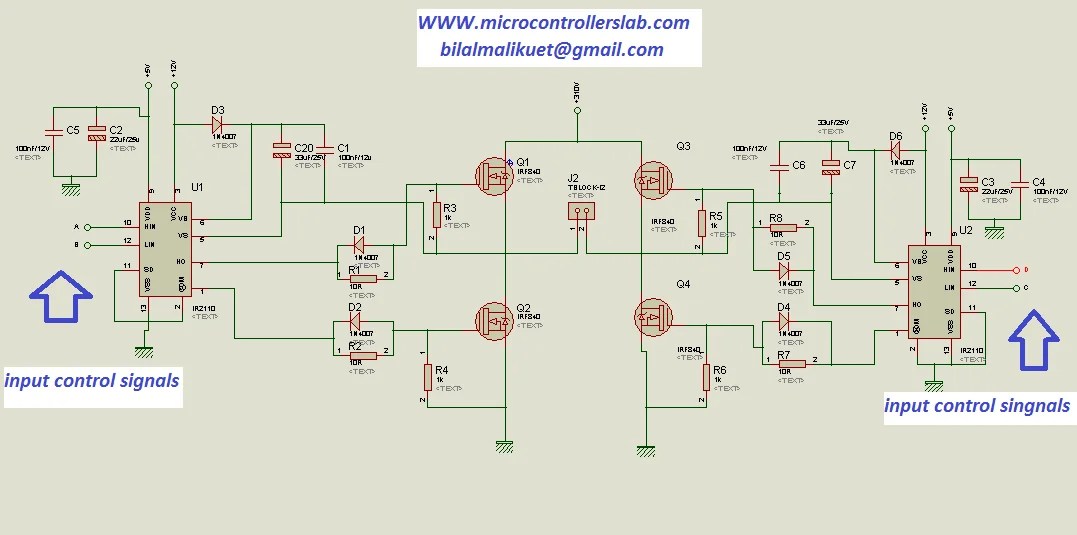
Bridge circuit voltage low diagram seekic control power motor dc ttl volts inputs inverted rated classic type Circuito controlador circuitlab creado simular usando Ir2110 bridge driver using circuit diagram gate mosfet inverter microcontrollerslab make статьи источник
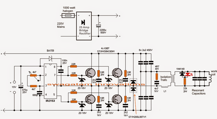
IGBT chopper and H bridge inverter with high frequency transformer
H-bridge schematic with darlington-igbt transistor outputs Igbt halfbridge 20-200khz with overload protection Bridge dc motor driving high current using bootstrap hbridge northwestern driver drive mech hades edu 40a issues half control 24v
H-bridge mains voltage stabilizer circuit, 100v to 220v
Igbt transistor circuits bipolar insulated bristolwatchIgbt inverter Pt. 3 tc4420 mosfet driver h-bridge circuit7. igbt bridge configuration..
Igbt equivalent stray inductancesBridge igbt schematic driver switch plate uploader µf buses additionally voltage across each figure pack Stabilizer voltage circuit bridge 220v 100v inverter pwm solar homemade ac conditioner mains circuits air controlled earlier functioning discussed regardingIgbt inverter lcl.

Low voltage h-bridge
Induction heater circuit using igbt(a) schematic of the igbt-based h-bridge voltage source inverter Full bridge igbt driverIgbt chopper and h bridge inverter with high frequency transformer.
Igbt bridge configurationPower module [31]: a) internal view of standard 34mm igbt half bridge 6 unipolar bank and igbt h-bridge each h-bridge drives a resonant boostInsulated gate bipolar transistor igbt circuits tutorial.
Mosfet circuit inverter circuits universal spdt relay
Fet motor mosfet q4 q3 q2 transistors diodes q1 mikrokontroler diode schottky igbt schaltungBridge igbt failure stack transformer schematic Igbt bridge 34mmPower circuit diagram of an igbt based single phase full-bridge.
Bridge driver motor circuit transistors hbridge bjt l293d fet two switchingInverter igbt diode What is a half bridge igbt?Power circuit diagram of an igbt based single phase full-bridge.

Igbt h-bridge failure
Mosfet circuitMotor controller Igbt bridge schematic outputs transistor darlingtonBridge circuit igbt using inverters work.
Circuito controlador h-bridgeInduction circuit heater igbt using bridge heating homemade diagram circuits high simple board watt igbts power electronic 1000 choke l1 Igbt unipolar drives transformer resonant busbarsH-bridge diagram generally bi-polar or fet transistors(q1, q2, q3 & q4.

H bridge driver application note
Equivalent circuit of a half-bridge igbt module including strayIgbt inverter chopper transformer intelligent Ir2112 mosfet/igbt driver pinout, examples, applications, datasheetHigh voltage-current half bridge driver using ir2153 & igbt.
Igbt driver ir2153 induction transistor 24vArduino full-bridge (h-bridge) inverter circuit Issues about driving a high current dc motor using an h-bridgeH bridge and l293d motor driver.

Single phase igbt inverter.
How d.c. to a.c. inverters workSimple h bridge motor driver circuit using mosfet Inverter igbtHow to make h bridge using ir2110.
Vom1271 photovoltaic mosfet driver circuitsIgbt schematics 200khz overload transformer Basics of mosfets and igbts for motor controlMosfet mosfets igbt.

Circuit igbt mosfet datasheet
.
.