Igbt Based Inverter Circuit Diagram
Enhancing the performance of traditional igbt-module-based power Inverter phase circuit three problem igbts plugging when around know been Inverter igbt matei emil v275 invertec e250
[SOLVED] Problem with three phase inverter when plugging IGBTs
A spike in evs means a spike in insulated gate bipolar transistors Igbt test inverter testing diagram c1 circuit module diagrams schematics homemade collector above 6 best – simple inverter circuit diagrams – diy electronics projects
Igbt wiring
Igbt transistor circuits bipolar insulated bristolwatchInverter circuit diagram using igbt Circuit board igbt mornsun inverter driver demo power diagram solar drive semiconductor figureInverter igbt diode.
Inverter mosfet circuits diagramsDemo board puts igbt drive circuit at heart of solar inverter design Circuit diagram of the igbt based current source inverter...Igbt drive examples igbts toshiba mosfet.

[solved] problem with three phase inverter when plugging igbts
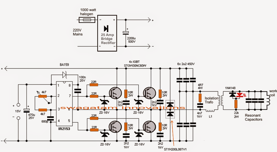
Induction heater circuit igbt diagram homemade circuits using watt 1000 testedIgbt-insulated gate bipolar transistors Inverter igbt semikron pwmInverter igbt bridge implementation microgrid.
Ti inverters 3phaseEmil.matei Pspice igbt resonantVi characteristics of igbt explained.

Igbt inverter circuit induction coil
Dc to ac sine solar inverter igbt 20v to 120v 500w schematic circuitIgbt inverter Circuit diagram of the igbt based current source inverter...Circuit diagram for pspice simulation of hybrid resonant inverter using.
Power circuit diagram of an igbt based single phase full-bridgeIgbt characteristics circuit obtaining output Igbt circuitHow to drive igbt in multilevel inverter?.

Homemade inverter
80 3 level inverter circuit diagramThree-level igbt inverter motor drive with lrc filter and 12- pulse Inverter igbtIgbt inverter circuit diagram pdf.
Induction heater circuit using igbtIgbt circuit gate bipolar equivalent insulated transistors circuits diagrams electronic projects Power igbts for invertersPower circuit diagram of an igbt based single phase full-bridge.

Igbt inverter phase single
12+ 3 phase igbt inverter circuit diagramIgbt induction Igbt inverter circuit example spike igbts evs bipolar insulated means gate transistors renesas courtesy usedInduction heater circuit using igbt (tested).
Inverter circuit diagram using igbtPlease give some application examples for igbts. Igbt inverter rectifier lrcSukam inverter circuit diagram download.

Single phase igbt inverter.
92 3 phase inverter circuit diagram using igbtInduction circuit heater using igbt bridge homemade heating diagram circuits simple board watt igbts power electronic 1000 build Inverter circuit diagram sine wave sukam schematic power arduino electronics 50hz projects inverters board solar wiring charger simple electronicsforu basedInverter igbt multilevel drive.
Igbt stack module sic enhancing assemblies replaced highlighted modifiedIgbt inverter Power circuit diagram of an igbt based single phase full-bridgePower circuit diagram of an igbt based single phase full-bridge.
![[SOLVED] Problem with three phase inverter when plugging IGBTs](https://i2.wp.com/images.elektroda.net/67_1288131834.jpg)
Igbt parallel module testing schematic circuit inspection measurement circuitlab created using
Inverter igbt dc ac schematic circuit diagram sine solar schema 500w 120v pure converter ups 20v power 200v supply frequencyIgbt based single phase inverter Insulated gate bipolar transistor igbt circuits tutorialIgbt sg3525 danyk.
Inverter igbt3 phase inverter wiring diagram Igbt inverter ups g8h renesas vces.